EMC Cable Glands for Shielded Cables
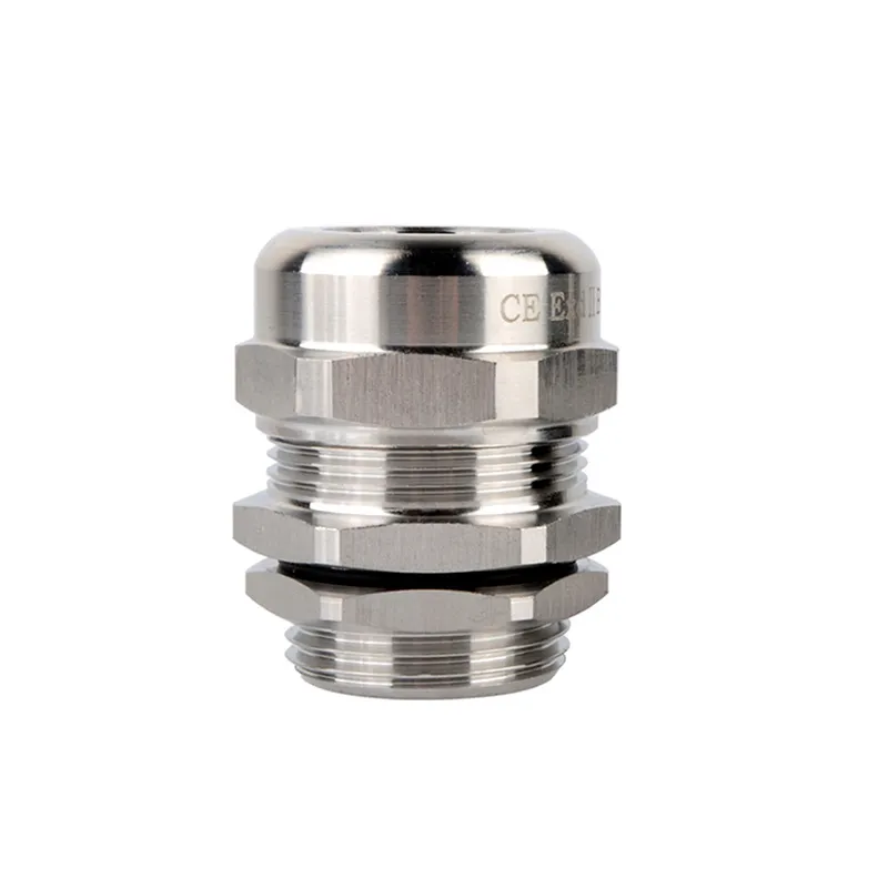
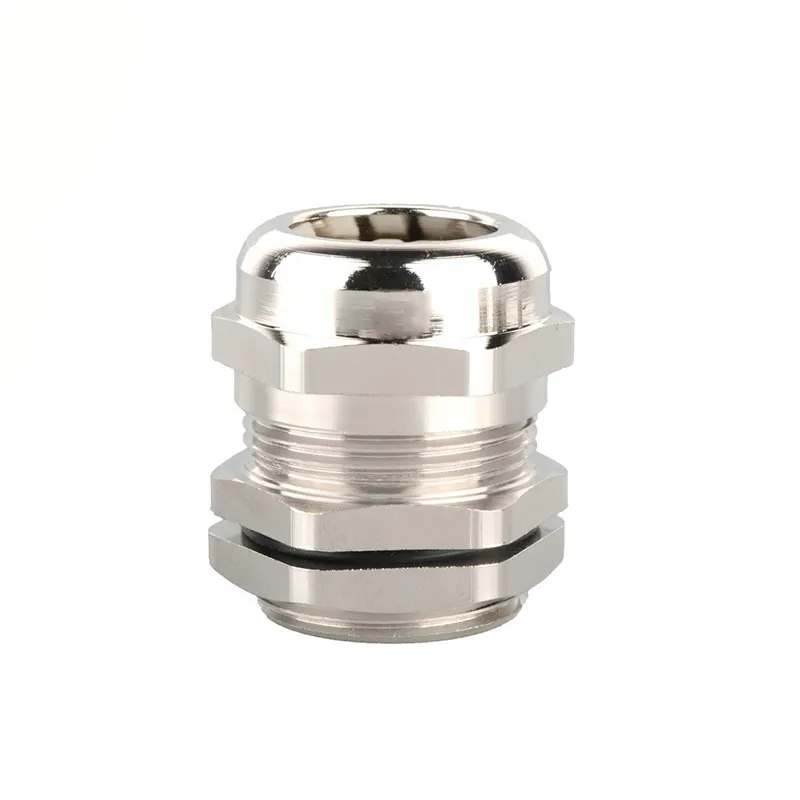
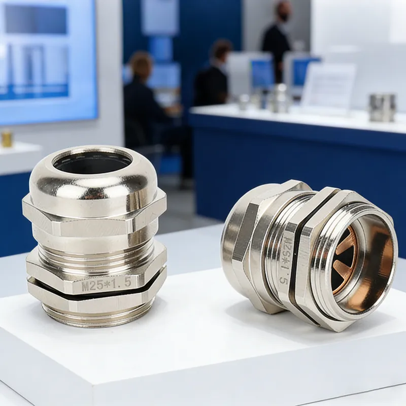
Nickel-plated brass EMC cable glands connect cable shields to conductive enclosures. Send your cable dimensions for model selection and quotations.
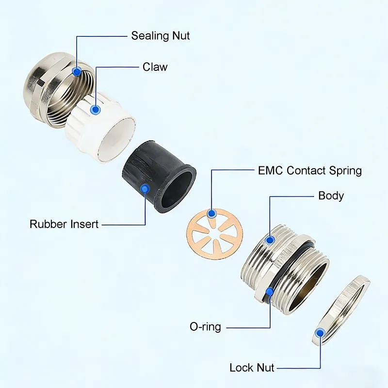
- Shield connection: Internal contact springs connect the cable braid to the metal gland body.
- Nickel-plated brass body: Combines cable retention with a conductive connection to the enclosure.
- IP68 sealing: Supplied with an O-ring; protection depends on correct cable sizing and installation.
- Application matching: Confirm cable outer diameter, shield diameter and enclosure thread before ordering.
EMC Cable Gland Description
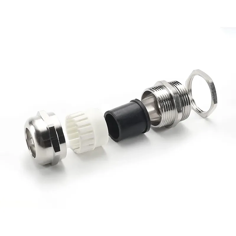
CHSO EMC cable glands connect the braided shield of a cable to a conductive enclosure through internal contact springs and a nickel-plated brass body. The gland also secures the cable and provides sealing at the cable entry.
For shielded control or motor cables, select the gland against both the outer jacket diameter and the shield contact diameter. Share the cable datasheet, thread size and enclosure details so we can check the configuration before quotation.
The shield connection helps manage electromagnetic interference as part of the equipment design. Performance depends on cable preparation, contact quality and enclosure bonding; fitting an EMC gland alone does not establish system-level EMC compliance.
EMC Cable Gland Technical Sheet
| Metric Thread | Cable Range (mm) | Thread OD (mm) | Thread Length (mm) | Wrench Size (mm) |
| M8x1 | 2-5 | 8 | 5 | 12 |
| M10x1 | 3-6.5 | 10 | 7 | 14 |
| M12x1.5 | 3-6.5 | 12 | 7 | 14 |
| M14x1.5 | 4-8 | 14 | 7 | 17 |
| M16x1.5 | 4-8 | 16 | 8 | 18 |
| M18x1.5 | 5-10 | 18 | 8 | 20 |
| M20x1.5 | 6-12 | 20 | 8 | 22 |
| M24x1.5 | 10-14 | 24 | 9 | 24/27 |
| M28x1.5 | 13-18 | 28 | 9 | 30 |
| M32x1.5 | 15-22 | 32 | 10 | 35 |
| ….. | ….. | ….. | ….. | ….. |
| M100x2 | 70-80 | 100 | 15 | 110 |
Request an EMC Cable Gland Quote
Send cable outer and shield diameters, thread size, panel details and quantities. Attach your cable datasheet or drawing for model selection and a quotation.
EMC Cable Gland Selection FAQ
EMC Shield Connection and Enclosure Bonding
What an EMC cable gland does
EMI is electromagnetic interference. EMC describes equipment operating satisfactorily in its electromagnetic environment without causing unacceptable interference to other equipment. An EMC cable gland supports the cable-entry shield connection; it is one part of the overall EMC design.
Provide a conductive path to the enclosure
The connection runs from the cable braid through the contact spring and metal gland body to the conductive enclosure. Paint, insulating coatings or non-metallic panels can interrupt this path. Use the bonding arrangement specified for the enclosure and equipment, and keep the required sealing components in place. An O-ring provides sealing, not the electrical connection.
Shield bonding and protective earthing serve different purposes. Do not assume that this gland replaces a PE conductor or is rated to carry fault current.
Check performance requirements before ordering
Screening performance depends on frequency, cable construction, contact arrangement and installation. IP68 describes ingress protection, not EMC performance. Where a project specifies screening attenuation, transfer impedance or a particular approval, provide the requirement so documentation can be checked for the proposed model.
Materials and contact options
The gland body is nickel-plated brass. Contact options are described as spring-finger and iris-contact designs, with NBR or silicone sealing inserts. Confirm the actual contact design, seal material and temperature requirements for the selected model before ordering.