

Multi-Hole and Flat Cable Glands
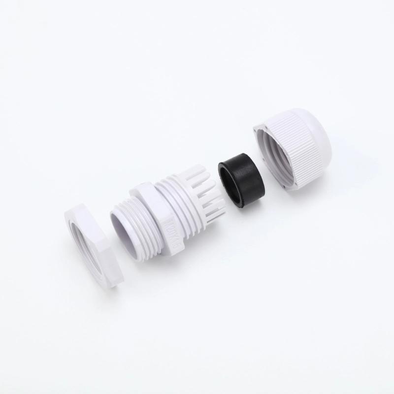
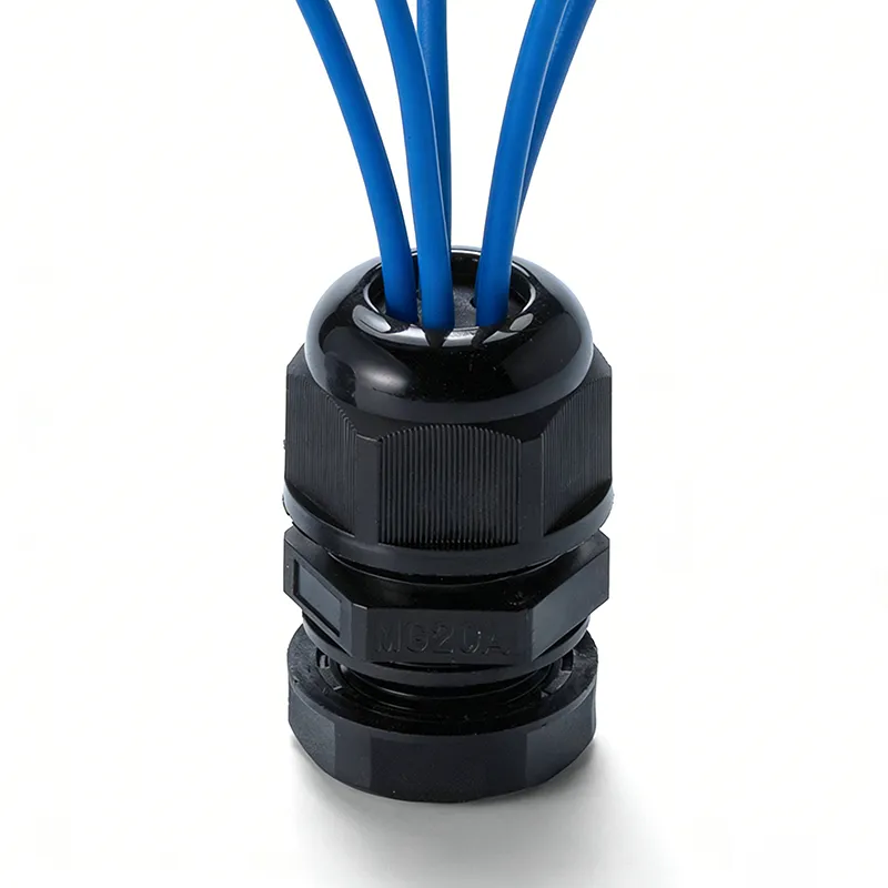
CHSO multi-hole cable glands route separate round cables through one entry; flat-hole inserts accommodate a matching flat cable profile.
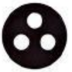
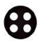
- Multi-hole configuration: One cable per insert hole. Select the hole layout and diameter for each cable.
- Flat cable configuration: The flat cable passes through the sealing insert at the front of the sealing nut. Match its width, thickness and outer profile.
- Panel connection: Specify the enclosure thread or clearance-hole arrangement and panel thickness.
- Sealing requirements: Identify the required protection rating, panel seal and treatment of unused insert holes before ordering.
Choose a Multi-Hole or Flat Cable Configuration
Choose a multi-hole cable gland when several separate round cables need to share one enclosure entry. Each cable occupies its own hole in the sealing insert; the number of conductors inside a cable is not the number of insert holes.
Choose a flat-hole cable gland for a flat-jacket cable. Selection depends on the cable width, thickness and corner profile, rather than an equivalent round diameter. The cable exits through the front of the sealing nut.
For an existing model, quote its complete reference and cable dimensions. For a custom insert, provide a dimensioned cable cross-section and the required hole layout. A matching insert does not by itself establish a protection rating or pull-out performance.
Model and Dimensional Reference
| Entries | Model | Cable Range(mm) | Thread O.D L2(mm) | Thread Length L1(mm) | Spanner Size ΔΦF (mm) |

| MG12A-H2-3 | 1-3 | 12 | 10 | 12-12.3 | |
| MG16A-H2-4 | 1.6-4 | 16 | 15 | 16-16.3 | |
| MG20A-H2-6 | 2.5-6 | 20 | 15 | 20-20.3 | |
| MG25A-H2-6 | 3-6 | 25 | 15 | 25-25.4 | |
| MG25A-H2-9 | 4.5-8.7 | 25 | 15 | 25-25.4 | |
| MG32A-H2-10 | 5-10 | 32 | 15 | 32-32.4 | |
![]() |
MG12A-H3-2 | 1.2-2.6 | 12 | 9 | 12-12.3 |
| MG16A-H3-4 | 1.6-4 | 16 | 15 | 16-16.3 | |
| MG20A-H3-3 | 1.5-3.5 | 20 | 15 | 20-20.3 | |
| MG20A-H3-5 | 2-5 | 20 | 15 | 20-20.3 | |
| MG25A-H3-5 | 2-5 | 25 | 15 | 25-25.4 | |
| MG25A-H3-8 | 4-8 | 25 | 15 | 25-25.4 | |
| MG32A-H3-10 | 5-10 | 32 | 15 | 32-32.4 | |
![]() |
MG12A-H4-2 | 1-2.3 | 12 | 9 | 12-12.3 |
| MG16A-H4-3 | 1.2-3 | 16 | 15 | 16-16.3 | |
| MG20A-H4-3 | 1.2-3 | 20 | 15 | 20-20.3 | |
| MG20A-H4-3. 7 | 2-4.5 | 20 | 15 | 20-20.3 | |
| MG25A-H4-5 | 2-5 | 25 | 15 | 25-25.4 | |
| MG25A-H4-7 | 3.5-7 | 25 | 15 | 25-25.4 | |
| MG32A-H4-9 | 4.5-9 | 32 | 15 | 32-32.4 | |

| MG16A-H5-2 | 1-2.5 | 16 | 15 | 16-16.3 | |
| MG20A-H5-3 | 1.2-3 | 20 | 15 | 20-20.3 | |
| MG20A-H5-4 | 1.7-4.2 | 20 | 15 | 20-20.3 | |
| MG25A-H5-3 | 1.5-3.5 | 25 | 15 | 25-25.4 | |
| MG25A-H5-6 | 3-6 | 25 | 15 | 25-25.4 | |
| MG32A-H5-8 | 4-8 | 32 | 15 | 32-32.4 | |
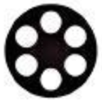
| MG16A-H6-2 | 1-2 | 16 | 15 | 16-16.3 | |
| MG20A-H6-3 | 1.2-3 | 20 | 15 | 20-20.3 | |
| MG25A-H6-3 | 1.5-3.5 | 25 | 15 | 25-25.4 | |
| MG25A-H6-5 | 2.4-5.3 | 25 | 15 | 25-25.4 | |
| MG32A-H6-7 | 3.5-7 | 32 | 15 | 32-32.4 | |

![]() |
MG16A-0610 | 6-10 | 16 | 15 | 16-16.3 |
| MG20A-0612 | 6.5-12 | 20 | 15 | 20-20.3 | |
| MG20A-0614 | 6-14 | 20 | 15 | 20-20.3 | |
| MG20A-0712 | 7-12 | 20 | 15 | 20-20.3 | |
| MG20A-0714 | 7-14 | 20 | 15 | 20-20.3 | |
| MG25A-0614 | 6-14 | 25 | 15 | 25-25.4 | |
| MG25A-0714 | 7-14 | 25 | 15 | 25-25.4 | |
| MG32A-0822 | 8-22 | 32 | 15 | 32-32.4 | |
| MG40A-1028 | 10-28.5 | 40 | 20 | 40-40.3 | |
| MG40A-0529 | 5.5-29 | 40 | 20 | 40-40.3 |
Request a Quote for Your Cable Configuration
Send the model reference, quantities by model, cable dimensions and enclosure connection details. For custom layouts, attach a cable cross-section and hole-layout drawing. Include the destination, operating environment and required documents so CHSO can prepare a configuration-specific quotation.
Information Needed for Selection
| Configuration | Cable information | Enclosure information |
|---|---|---|
| Multi-hole | Number of separate cables; outside diameter and tolerance of each cable; occupied and unused holes | Thread standard and size, or clearance-hole drawing; panel thickness; sealing arrangement |
| Flat-hole | Width, thickness, tolerances and outer profile; a cross-section drawing or sample where available | Thread standard and size, or clearance-hole drawing; panel thickness; sealing arrangement |
A nominal thread size is not an installation-hole specification. Check the selected model against the enclosure drawing before machining.
FAQs
Match the Insert to the Cable Layout
List each separate cable and its outside diameter, including production tolerances. Record which insert holes will be occupied. For a flat cable, provide the actual cross-section: width, thickness and corner shape all affect fit. Do not select an insert from cable core count alone.
Confirm the Supply Configuration and Documents
Your quotation should identify the gland body, sealing insert, sealing nut, panel-sealing accessory, locknut and any unused-hole plugs, stating which items are included or ordered separately. Specify material, colour and environmental requirements with your enquiry.
Where a project requires an IP test report or other compliance document, request the document for the selected model, material and assembly. Certification of another cable gland series does not establish coverage for this configuration.
Related News
To specify a multi-hole cable gland, provide the number of cables, the outside diameter of each cable and the enclosure […]