

CHSO breather vents, also called venting plugs, allow air exchange between an enclosure and its surroundings to help balance pressure changes. Choose PA66 plastic, 304 stainless steel or nickel-plated brass using the separate specification tables below.
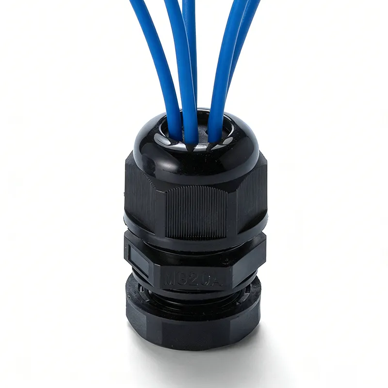
These components fit a dedicated enclosure opening. They do not carry or clamp a cable. Match the thread and pitch, required airflow, wall thickness and available space before ordering.
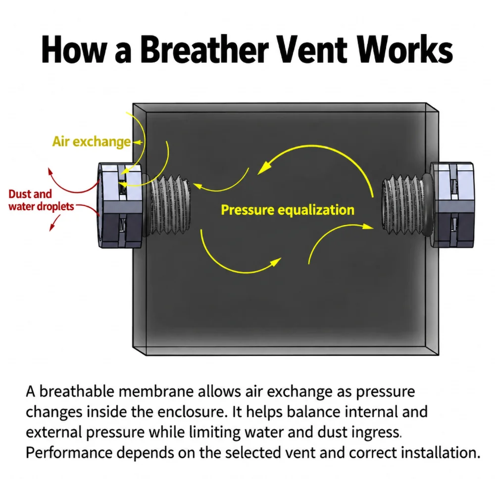
How a Breather Vent Works
Temperature changes can create a pressure difference between the inside and outside of a housing. A breathable membrane lets air pass to help equalize that pressure while limiting water and dust ingress. It can help reduce condensation risk, but it is not an active cooling device and does not guarantee a dry enclosure.
PA66 Plastic Breather Vents
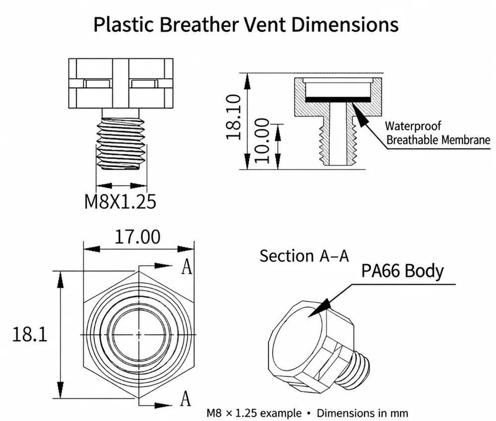
Body: PA66. Colours: black and white-grey. These standalone vents allow air exchange through a waterproof breathable membrane to help balance enclosure pressure. They do not provide cable entry or cable strain relief.
| Thread Size | Airflow at ΔP = 70 mbar (mL/min) | Thread Length (mm) | Total Length (mm) | Thread Diameter (mm) | Wrench Size (mm) |
|---|---|---|---|---|---|
| M5 × 0.8 | ≥ 600 | 7 | 13 | 5 | 12 |
| M6 × 1.0 | ≥ 600 | 7 | 13 | 6 | 12 |
| M8 × 1.0 | ≥ 600 | 7 | 12.5 | 8 | 12 |
| M8 × 1.25 | ≥ 1500 | 10 | 18 | 8 | 17 |
| M10 × 1.5 | ≥ 1500 | 10 | 18 | 10 | 17 |
| M12 × 1.0 | ≥ 1500 | 10 | 16 | 12 | 16 |
| M12 × 1.5 | ≥ 1500 | 10 | 16 | 12 | 16 |
| M12 × 1.5 | ≥ 1500 | 10 | 18 | 12 | 17 |
| M16 × 1.5 | ≥ 4000 | 10 | 18 | 16 | 22 |
| M20 × 1.5 | ≥ 4500 | 10 | 18 | 20 | 27 |
| M24 × 1.5 | ≥ 7000 | 15 | 24 | 24 | 36 |
| M32 × 1.5 | ≥ 8000 | 15 | 25 | 32 | 45 |
| M40 × 1.5 | ≥ 8500 | 15 | 24 | 40 | 56 |
Airflow values above are per vent at a differential pressure of 70 mbar (7 kPa); this is a test condition, not a working-pressure rating. The two M12 × 1.5 versions have different overall and wrench dimensions. Specify both dimensions when ordering.
Plastic series technical data: temperature range −40°C to +150°C; hydrostatic resistance >100 mbar for 30 minutes; moisture vapour transmission 5000 g/m²/24 h. The stated membrane air permeability is 1.2 L/min/cm² at 70 mbar and is separate from the per-vent airflow listed above. Request applicable test conditions and the selected model drawing for project approval.
304 Stainless Steel Breather Vents
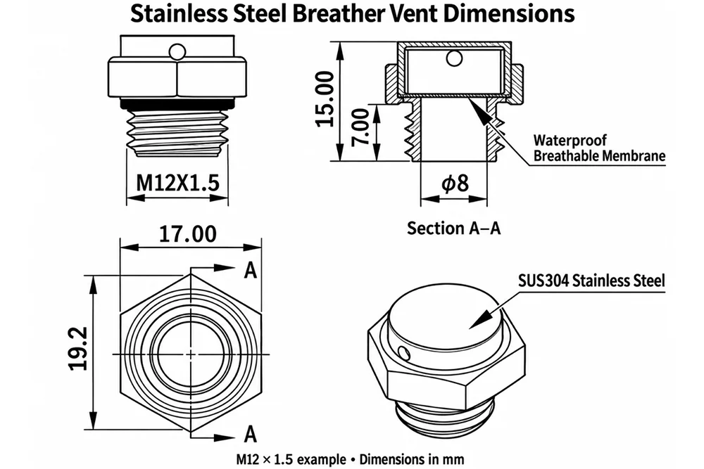
Natural-finish 304 stainless steel bodies. Select Metric or G thread and check the exact body dimensions. The three M12 × 1.5 versions differ in thread length and overall length.
| Thread Size | Color | Material | Thread Length (mm) | Thread Diameter (mm) | Total Length (mm) | Membrane Air Permeability | Spanner Size (A/F) |
|---|---|---|---|---|---|---|---|
| M25 × 1.5 | Natural | 304 Stainless Steel | 8 | 25 | 23 | ≥ 1.2 L/min/cm² @ 70mbar | 30 |
| M20 × 1.5 | Natural | 304 Stainless Steel | 10 | 20 | 19.5 | ≥ 1.2 L/min/cm² @ 70mbar | 22 |
| M16 × 1.5 | Natural | 304 Stainless Steel | 10 | 16 | 19.5 | ≥ 1.2 L/min/cm² @ 70mbar | 22 |
| M12 × 1.5 | Natural | 304 Stainless Steel | 7 | 12 | 15 | ≥ 1.2 L/min/cm² @ 70mbar | 17 |
| M12 × 1.5 | Natural | 304 Stainless Steel | 6 | 12 | 18 | ≥ 1.2 L/min/cm² @ 70mbar | 17 |
| M12 × 1.5 | Natural | 304 Stainless Steel | 6 | 12 | 14 | ≥ 1.2 L/min/cm² @ 70mbar | 17 |
| M10 × 1 | Natural | 304 Stainless Steel | 8 | 10 | 16.5 | ≥ 1.2 L/min/cm² @ 70mbar | 17 |
| M8 × 1.25 | Natural | 304 Stainless Steel | 7 | 8 | 16.2 | ≥ 1.2 L/min/cm² @ 70mbar | 14 |
| M6 × 1 | Natural | 304 Stainless Steel | 7 | 6 | 15 | ≥ 1.2 L/min/cm² @ 70mbar | 10 |
| M5 × 0.8 | Natural | 304 Stainless Steel | 7 | 5 | 15 | ≥ 1.2 L/min/cm² @ 70mbar | 10 |
| G1/4 | Natural | 304 Stainless Steel | 10 | Request drawing | 18 | ≥ 1.2 L/min/cm² @ 70mbar | 17 |
| G3/8 | Natural | 304 Stainless Steel | 10 | Request drawing | 19.5 | ≥ 1.2 L/min/cm² @ 70mbar | 22 |
| G1/8 | Natural | 304 Stainless Steel | 8 | Request drawing | 16.5 | ≥ 1.2 L/min/cm² @ 70mbar | 14 |
The values in L/min/cm² describe membrane air permeability at 70 mbar, not the total airflow through an assembled vent. Request per-vent airflow for sizing. For G-thread versions, confirm the thread dimensions from the selected model drawing.
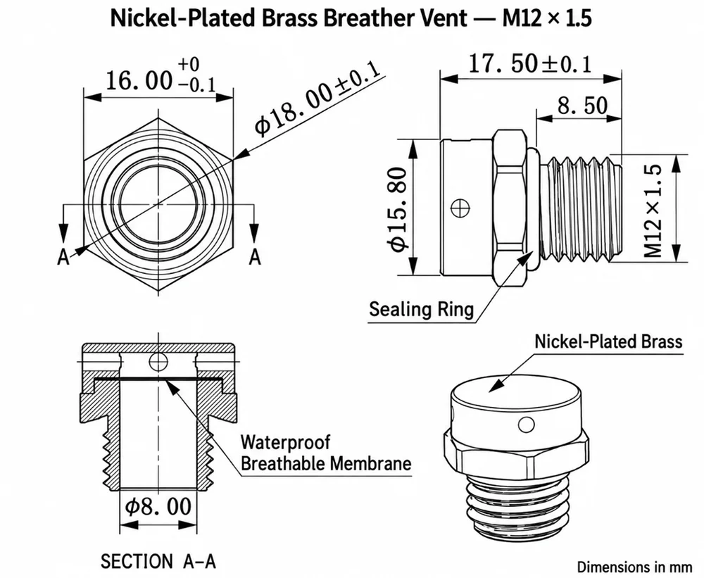
Nickel-Plated Brass Breather Vents
Nickel-plated brass bodies with Metric threads. Check the pitch as well as the nominal size: M10 and M12 are available with different pitches.
| Thread Size | Body Material | Thread Length (mm) | Thread Diameter (mm) | Total Length (mm) | Membrane Air Permeability | Spanner Size (A/F) |
|---|---|---|---|---|---|---|
| M5 × 0.8 | Nickel-Plated Brass | 7 | 5 | 15 | ≥ 1.2 L/min/cm² @ 70mbar | 10 |
| M6 × 1 | Nickel-Plated Brass | 7 | 6 | 15 | ≥ 1.2 L/min/cm² @ 70mbar | 10 |
| M8 × 1.25 | Nickel-Plated Brass | 8 | 8 | 17 | ≥ 1.2 L/min/cm² @ 70mbar | 14 |
| M10 × 0.75 | Nickel-Plated Brass | 8 | 10 | 17 | ≥ 1.2 L/min/cm² @ 70mbar | 14 |
| M10 × 1.5 | Nickel-Plated Brass | 8 | 10 | 17 | ≥ 1.2 L/min/cm² @ 70mbar | 14 |
| M12 × 1 | Nickel-Plated Brass | 8.5 | 12 | 17.5 | ≥ 1.2 L/min/cm² @ 70mbar | 16 |
| M12 × 1.5 | Nickel-Plated Brass | 8.5 | 12 | 17.5 | ≥ 1.2 L/min/cm² @ 70mbar | 16 |
| M16 × 1.5 | Nickel-Plated Brass | 10 | 16 | 19 | ≥ 1.2 L/min/cm² @ 70mbar | 20 |
| M20 × 1.5 | Nickel-Plated Brass | 10 | 20 | 19 | ≥ 1.2 L/min/cm² @ 70mbar | 22 |
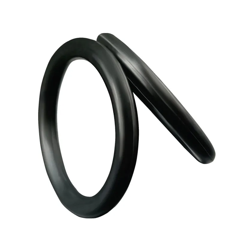
Membrane air permeability is expressed per unit area. It cannot be compared directly with the plastic table’s per-vent airflow. Confirm the required airflow and sealing-ring specification with the quotation.